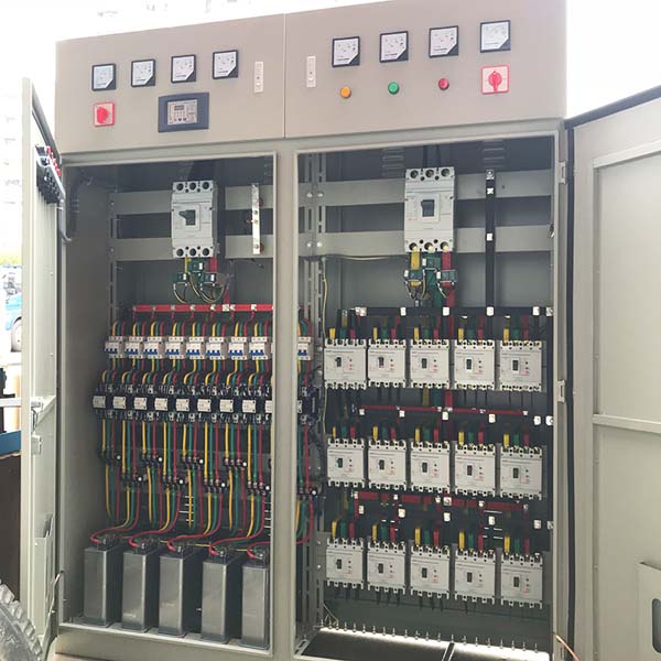


440V 300kvar cylinder type power capacitor bank
Low voltage automatic power factor correction panels(APFC Panel) provide a cost-effective, user friendly, reliable solution for power factor correction. They are a more efficient alternative to individual motor capacitors, especially in large industrial facilities.
LV APFC Panel are designed to provide power factor correction with a single installation on the main plant bus and are ideal for applications where plant loading is constantly changing, resulting in the need for varying amounts of reactive power. The solid state reactive power controller reacts to a current signal from a single remote current transformer (provided by the customer), measures plant power factor and adjusts system load requirements in selected kVAr steps in order to maintain the desired target power factor.

Features LV APFC Panel
Benefits LV APFC Panel
Applications LV APFC Panel
automatic capacitor banks are widely used for fluctuating loads such as motors, variable frequency drives, melting furnace from Steel Rolling mills,Chemical industry,Cement plant, Suger plant, Textile, Hospitals, Hotels, Building segment,Automobile industry,Oil and gas industry,public grid etc.


 |
 |
 |
 |
 |
 |
 |
| Performance |
SVG (Static VAR Generator) | Switched Capacitor Bank System |
Mode of Operation |
The SVG detects the load current on a real-time basis through an external CT and determines the reactive content of the load current. The data is analysed and the SVG’s controller drives the internal IGBT’s by using PWM signals to make the inverter produce the exact reversing reactive current of the corresponding load reactive current. | The system detects the load current on a real-time basis through an external CT and determines the reactive content of the load current. The data is analysed and the system’s controller switches in the required amount of reactive current in steps, depending on the amount of reactive current available to it in that moment from the capacitor bank. |
Compensation method |
The SVG performs as a controlled current source, thus obtaining a power factor of 0.99 lagging whilst avoiding over-compensation and under-compensation. |
Traditional PFC systems use capacitors in groups. Their output current is in fixed steps (50kVAr, 25kVAr, 12.5kVAr, 6.25kVAr) which usually leads to over or under-compensation. |
On-going costs |
The SVG does not require a maintenance contract. It simply requires that the unit is kept clean. Aside from the initial purchase cost, on-going costs are negligible. |
Capacitor bank style PFC systems are typically sold with a maintenance contract which is an on-going monthly charge to pay for regular maintenance and the cost of replacement parts like the capacitors, contactors, fuses, etc. |
Response Time |
The complete response time of the SVG is less than 15ms and the dynamic response time is less than 50μs. The SVG can track the dynamics of the load and compensate instantaneously in almost real-time. |
Capacitor bank style PFC systems take at least 20ms – 40s to perform compensation depending upon whether the switching is done via a solid state switch or a contactor. |
3 Phase Operation |
The SVG measures and provides dynamic kVAr compensation throughout all three phases. |
A switched capacitor bank style PFC system measures only one phase and provides stepped kVAr compensation only to that phase, irrespective of what the other two phases need. |
Load Imbalances |
The SVG can, if required, balance the phase currents to further lower the peak kVA presented to the grid (or energy authority). |
Capacitor banks with Delta connected capacitors cannot balance the load currents in a three phase system. |
Wall-Mount Solutions |
The SVG is available in the following wall-mount options: 50kVAr, 100kVAr & 200kVAr. They can be parallel connected in a ‘Master / Master / Master’ type arrangement. This ‘plug and play’ system provides the safest continuous operation. If one unit is shut down for whatever reason the remaining modules remain in operation until the alarm is attended to or the situation resolved. |
Limited range. |
Resonance |
The capacitance of the SVG does not require the installation of a de-tuning reactor. Performing as a current source and an active compensation device the SVG has been designed to not be affected by resonance. |
Traditional PFC systems are affected by resonance, which is detrimental to the capacitors. To lower the risk, de-tuning reactors are introduced into the circuit to lower the resonant frequency below that of the lowest harmonic in the circuit. |
Harmonics |
The SVG can operate in harmonically rich environments of up to 15% THDV without detriment to itself or its performance. |
Even with the use of de-tuned reactors, harmonics play a major role in shortening the lifespan of capacitors and contributing to their destruction. |
Load Type |
The SVG can correct both a lagging and a leading power factor, as well as work with a traditional capacitor type PFC system to eliminate over and under compensation. |
Capacitor bank style PFC systems can only compensate for inductive loads. |
Operation at low voltages |
Designed with an active compensation circuit. Therefore the voltage of the grid has little influence on the compensation capacity. The output of reactive current matches the working conditions even when the voltage of the power grid is low. |
Capacitor output is subject to the voltage of the grid, so if the grid voltage is low the output of the capacitors will be low, resulting in a decline in available compensating capacity, under-compensation and possible fault conditions. |
Sizing |
The compensation capacity of the SVG is the same as the installed capacity. Therefore for a given compensation effect, the capacity of the SVG may be 20%-30% less than that of a standard capacitor type PFC system. |
To better suit the changing dynamics of the load, a traditional capacitor type PFC system needs to be oversized and to have a greater number of smaller steps to better suit the application. This increases the cost. |
| ROI (Return on Investment) |
The SVG does not require a maintenance contract. It simply requires that the unit is kept clean. Aside from the initial purchase cost, on-going costs are negligible. |
When estimating the ROI for capacitor bank style PFC systems, apart from the initial cost of the system, other factors over the medium to long term must be considered, including the on-going cost of the maintenance contract and replacement parts like the capacitors, contactors, fuses, etc. |