


"The vacuum circuit breaker is named after the high vacuum of its interrupting medium and the insulation medium of the contact gap after interrupting; it has the advantages of small size, light weight, suitable for frequent operation and interrupting without maintenance, and is more popularly used in the distribution network. The vacuum circuit breaker is an indoor power distribution device in the 3-10kV, 50Hz three-phase AC system, which can be used for the protection and control of electrical equipment in industrial and mining enterprises, power plants and substations, and is especially suitable for places requiring oil-free, less maintenance and frequent operation.
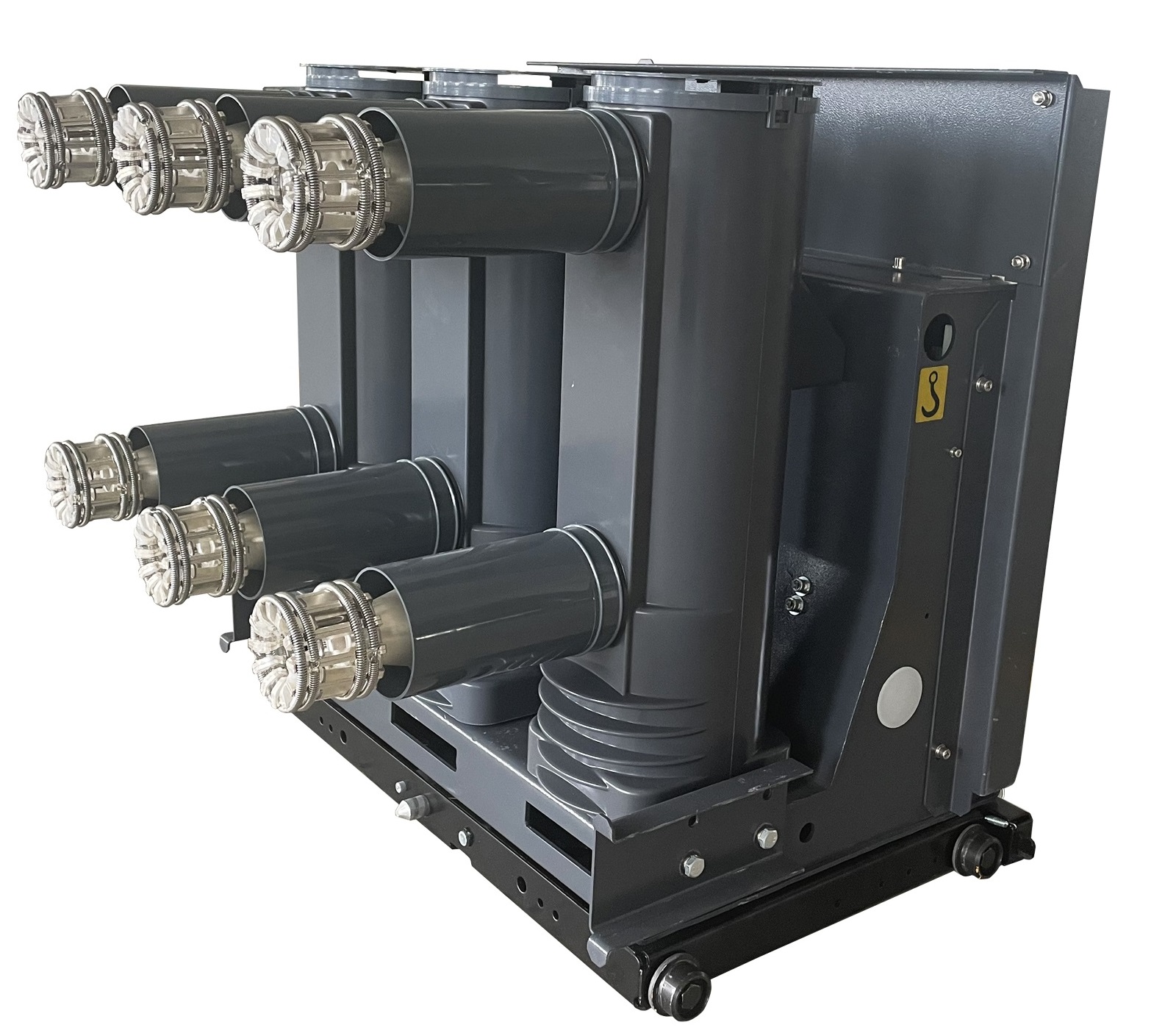
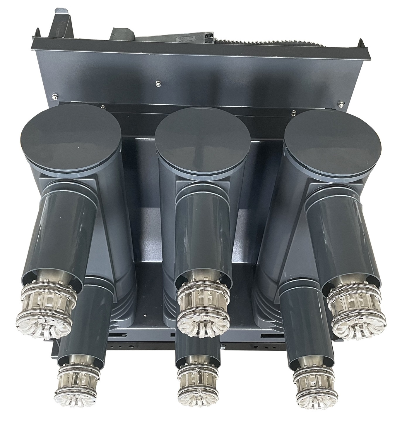
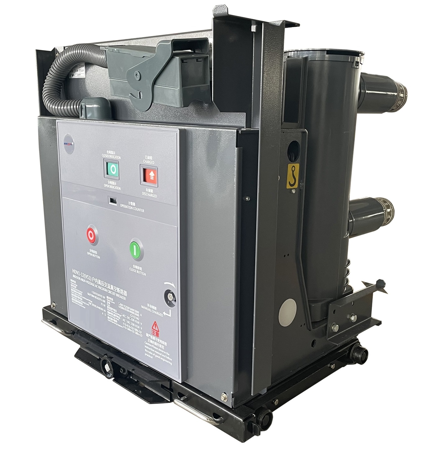
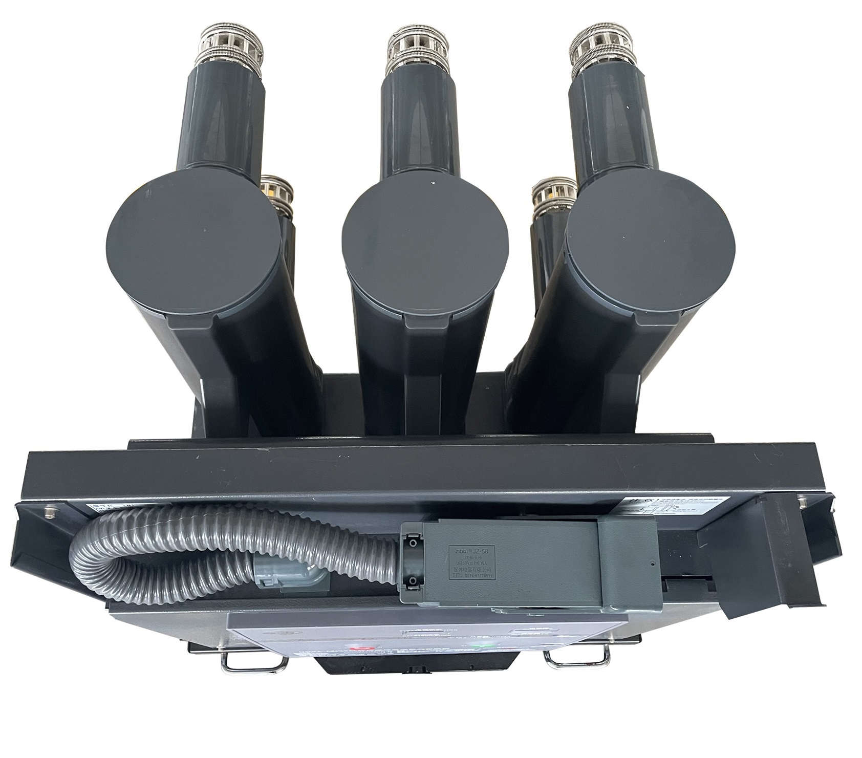
According to the different types of switches there are external shield type ceramic vacuum interrupters, intermediate sealed cup type longitudinal magnetic field miniaturised vacuum interrupters, internal sealed glass bubble interrupters, the basic structure of which is as follows.
①Gas-tight insulation system (shell)
②Conductive system
③Shielding system
Table 1. Technical parameters of ZN63A(VS1)-12/24kV high voltage ac vacuum circuit breaker
|
No. |
Item |
unit |
Parameter |
|||
|
1 |
Rated Voltage |
kV |
12 |
24 |
||
|
2 |
Rated Frequency |
Hz |
50/60 |
|||
|
3 |
Rated lightning impulse withstand voltage(peak) |
kV |
42 |
55 |
||
|
4 |
Rated power frequency withstand voltage (1s)(Effective) |
kV |
75 |
125 |
||
|
5 |
Rated short-circuit breaking current |
kA |
20、25、31.5、40 |
|||
|
6 |
Rated current |
A |
630、1250、1600、2000、2500、3150 |
|||
|
7 |
Rated peak withstand current |
kA |
50、63、80、100 |
|||
|
8 |
Rated short time withstand current |
kA |
20、25、31.5、40 |
|||
|
9 |
Rated short circuit continuous time |
s |
4 |
|||
|
10 |
Rated short-circuit on/off current |
kA |
50、63、80、100 |
|||
|
11 |
Percentage of the dc component of the rated short-circuit breaking current |
% |
35 |
|||
|
12 |
Rated operation sequence |
|
O-0.3s-CO-180s-C |
|||
|
13 |
Rated single/back-to-back capacitor bank breaking current |
A |
630/400 |
630/400 |
630/400 |
800/400 |
|
14 |
Rated short-circuit current breaking |
times |
50 |
50 |
50 |
30 |
|
15 |
Mechanical life |
times |
10000 |
|||
|
16 |
Rated opening/closing operation voltage |
V |
AC/DC110 AC/DC220 |
|||
|
17 |
Rated voltage of energy storage motor |
V |
AC/DC110 AC/DC220 |
|||
|
18 |
Power frequency withstand voltage of secondary circuit |
V |
2000 |
|||
|
No. |
Item |
unit |
Parameter |
|
|
1 |
Rated operation voltage |
Closing tripping coil |
V |
AC/DC110 AC/DC220 |
|
Opening tripping coil |
||||
|
2 |
Working current |
Closing tripping coil |
A |
1.1 |
|
Opening tripping coil |
||||
|
3 |
Power of energy-storage motor |
W |
70、80 |
|
|
4 |
Working voltage of energy-storage motor |
V |
AC/DC220 |
|
|
5 |
Motor energy storage time |
S |
≤15 |
|
|
6 |
Aux.contact |
pair |
6NO,6 NC |
|
|
Breaking capacity |
AC/10A;DC/5A |
|||
In addition to meet the requirements of the design drawings, the assembled and adjusted circuit breakers shall also meet the requirements listed in table 3.
|
No. |
Item |
unit |
Parameter |
|||||
|
1 |
Contact open distance |
mm |
11±1 |
|||||
|
2 |
Contact trip |
mm |
3.5±0.5 |
|||||
|
3 |
Average opening speed |
m/s |
1.1±0.2 |
|||||
|
4 |
Average closing speed |
m/s |
0.6±0.2 |
|||||
|
5 |
Contact closing bounce time |
ms |
≤2 |
|||||
|
6 |
At the different period of 3-phase consistency |
ms |
≤2 |
|||||
|
7 |
Opening time (under the rated operation voltage ) |
ms |
≤50 |
|||||
|
8 |
Closing time( under the rated operation voltage) |
ms |
≤100 |
|||||
|
9 |
Primary resistance |
Rated current |
mW |
630A |
1250A |
1600A |
2000A |
2500、3150A |
|
Fixed type VCB |
≤45 |
≤40 |
≤35 |
≤30 |
≤25 |
|||
|
Withdrawable type VCB |
≤50 |
≤45 |
≤40 |
≤35 |
≤30 |
|||
|
10 |
Closing Spring energy-storage time |
s |
12 |
|||||
Working Principle
The working principle of the vacuum circuit breaker is: when the movable and static contacts are divided under the action of the operating mechanism, an electric arc is generated between the contacts, and the surface of the contacts volatilizes steam at high temperature, due to the special shape of the contact design, a magnetic field is generated when the current passes through, the arc moves rapidly along the tangential direction of the contact surface under the action of this magnetic field, and some of the metal steam condenses on the metal cylinder (shield), and the arc is extinguished when it naturally crosses zero. The arc is extinguished, and the dielectric strength between the contacts is rapidly restored
6.1 Assembly adjustment inspection shall be carried out according to the product drawing and this technical condition, and shall meet the requirements of article 5 of this technical condition.
6.2 Mechanical operation test shall be conducted in accordance with IEC62271-100
6.2.1 Rated operating voltage shall be applied to the motor, closing tripping electromagnet and opening tripping electromagnet. Five times of closing spring energy storage and closing / opening operation shall be carried out. The operation shall be normal and meet the requirements of article 5 of this technical condition.
6.2.2 Manual closing spring energy storage, manual button closing, operating 5 times, the action should be normal.
6.2.3 The rated operating voltages of 85% and 110% are respectively applied to the motor, and the closing spring energy storage operation is carried out for 5 times respectively, meeting the requirements of article 5.2 of this technical condition.
6.2.4 Rated operating voltages of AC 85%, DC 80% and 110% are respectively applied to the closing and tripping electromagnet.
6.2.5 The rated operating voltages of 65% and 120% are respectively applied to the opening electromagnet,operate 5 times respectively and the action should be normal.Rated operating voltage of 30% shall be applied to the opening operation for 3 times consecutive and the circuit breaker shall not be tripping.
6.2.6 One time automatic reclosing operation. Operate O-0.3s-CO for 5 times under the rated voltage and the action shall be normal.
6.2.7 Mechanical interlock test for closing operation : The circuit breaker is in the closing position , the spring of closing is in the condition of energy-storage, push closing by manual for 3 times, the closing spring shall not be be released.
6.3 Main circuit resistance measurement According to the standard IEC 62271-100. Before /after the mechanical life test and before/ after the temperature rise test, test it one time respectively and the measured value shall conform to the provisions of table 3.
For the temperature rise test before mechanical life test, the difference between the resistance of the main loop measured after the test when the sample is cooled to the ambient air temperature and that measured before the temperature rise test should be less than 20%.
6.4 Temperature rising test.
According to the standard IEC 62271-100.
6.4.1 Before and after the mechanical life test ,test it one time respectively. The temperature rise of the current-carrying conductor in the vacuum arc extinguishing chamber is not measured.
6.4.2 The rated voltage is applied to the solenoid coil of the opening /closing /tripping of the operating mechanism. 10 times of continuous closing and opening is applied, and the time interval between the two electrification is 10s. The temperature rise of each coil is measured by the resistance method, and the temperature rise shall not exceed 65K.
6.5 Insulation Test.
6.5.1 Power frequency withstand voltage test and lightning impulse withstand voltage test shall be conducted in accordance with IEC 62271-100, and the test voltage shall be in accordance with table 1.
6.5.2 The insulation test of the auxiliary circuit shall be conducted in accordance with the provisions of IEC 62271-100, and the power frequency test voltage for 1 min on the ground shall be 2000V.
6.5.3 For inter-turn insulation test of various coils in the operating mechanism, the rated voltage of the DC coil is 2.5 times 1min, and the rated voltage of the AC coil is 3.5 times 1min.
6.5.4 The insulation of the energy storage motor shall be measured with a 500V megohm meter, and its ground resistance shall be greater than 0.5 megohm.
6.6 Short-circuit breaking & on/off test is in accordance with the provisions of IEC 62271-100
6.7 Rated short-circuit breaking current & breaking times test. The total breaking times of rated short-circuit breaking current is 50 (30) times, including 20 (12) times of single breaking, 15 (9) times of combined breaking, and 5 (3) times of rated operation sequence. When the breaking times test and breaking and on/off ability test are combined, the breaking times of test mode 4 and test mode 5 are included in the rated breaking times of short-circuit breaking current. 6.9 After the rated short-circuit breaking, on/off capacity and rated short-circuit breaking current breaking times test, power frequency and lightning impulse withstand voltage test shall be carried out on the fracture in accordance with GB/T16927.1, and the voltage withstand value shall not be lower than the value specified in table 1.
6.8 Short-time withstand current and peak withstand current test Is in accordance with IEC 62271-100.
6.9 Open and close capacitor bank test(Suitable for circuit breakers with this requirement)is in accordance with IEC 62271-100.
6.10 Step out breaking,open/close testing (Suitable for circuit breakers with this requirement)is in accordance with IEC 62271-100.
6.11 Breaking test for non-phase ground fault:The user negotiates it with the manufacturer. According to IEC 62271-100.